Vectorworks software offers many powerful tools, giving you the flexibility to approach a design task in a variety of ways. With so many options, how do you determine the best workflow for your needs?
In this article, you’ll explore key modeling techniques used by Vectorworks product experts to create the custom record player featured at the top of this page. Along the way, you’ll gain valuable insights into commonly used tools and their applications, helping you make more informed decisions about your own modeling process.
Best of all, every technique showcased here is available in Vectorworks Fundamentals, meaning you can achieve stunning, professional-quality models no matter which Vectorworks product you use.
Design Layer Navigation
Vectorworks 2025 introduced On-Screen View Control and Object-Level Visibility, two features designed to streamline the way you move around your Vectorworks file. Though they’re not technically “modeling features,” they were used extensively in the creation of this turntable for the host of benefits they provide to any modeling process.
On-Screen View Control gives you access to a cube at the bottom left of your design layer. You can use this cube to rotate and “fly” around your model. Edges, corners, and faces of the cube are also intuitively mapped to the viewing options you’re used to, like top/plan and all the various isometric views.
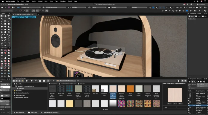
Object-Level Visibility is great for working on the kinds of intricate details in this model. Instead of manipulating objects’ visibilities with classes and layers — which can get tedious if you’re working with a lot of small, unrelated details — you can use this feature to quickly isolate a single object so you can focus on that object alone.
![]()
A turntable cabinet shown “ghosted” via the Object Visibility feature.
Sweep command
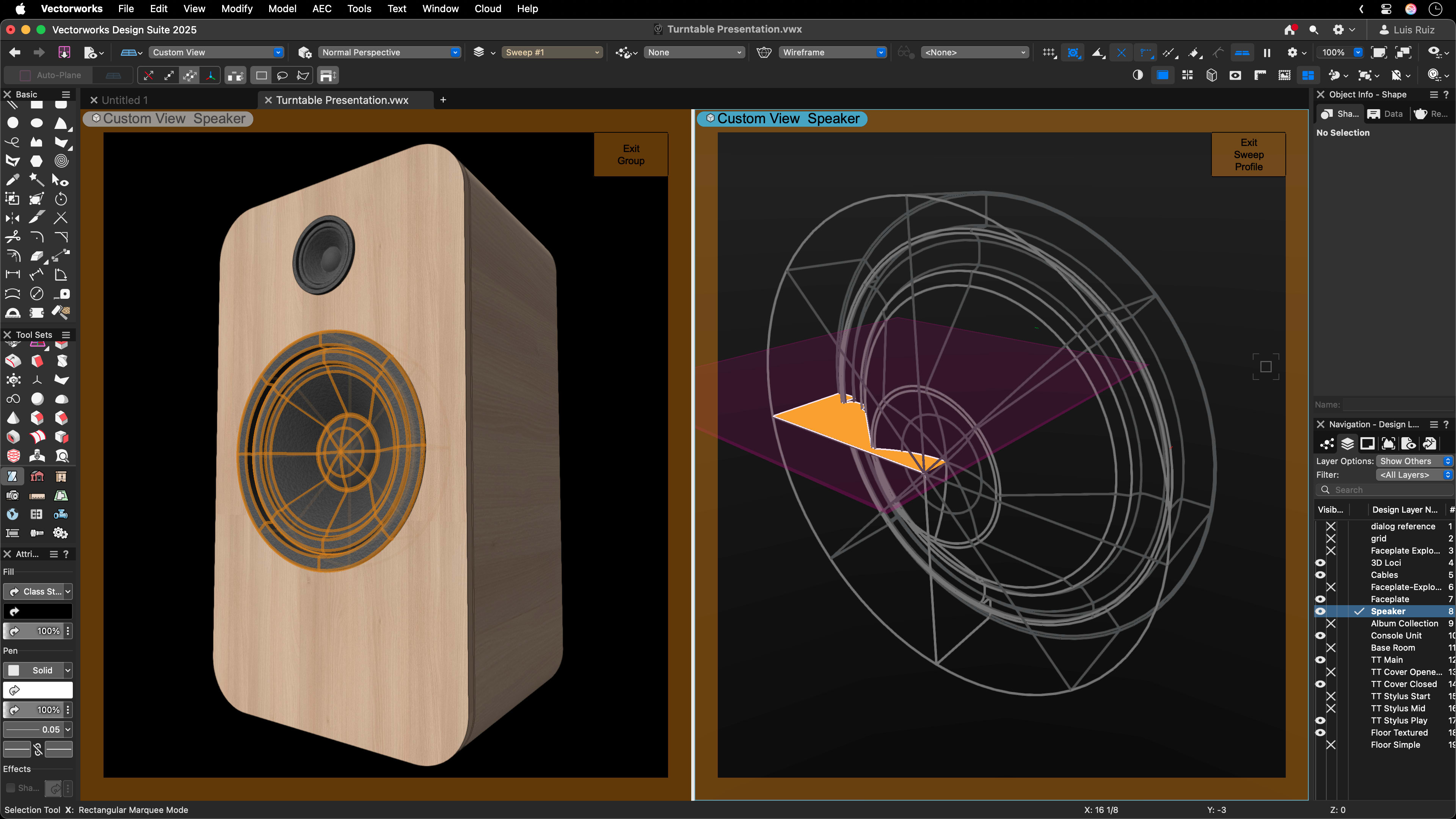
Using the Sweep command, you can start from 2D linework to generate 3D shapes around a set point. This technique is responsible for the circular speaker in the record player, as shown below.
With Arc Angle set to 360 degrees, the software will rotate — or “sweep” — this shape around a central point, also known as a centroid, to generate 3D geometry. This command is useful for creating unique shapes in very little time.
Add/Subtract Solids
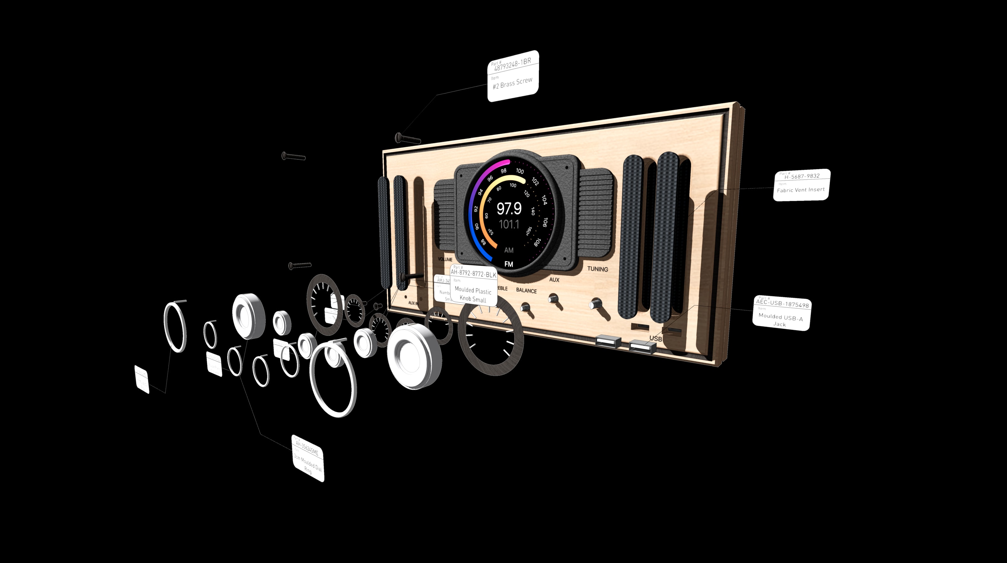
The Add, Intersect, and Subtract Solids commands allow you to combine or subtract two or more different 3D objects. Highlighting two objects and selecting the Add Solids command will convert the two objects into one. The Subtract Solids command is useful for clipping away a section from a base object by using a second object to define the shape of the subtraction.
The Subtract Solids command was used on this turntable to create the holes where the knobs and buttons go at the base of the console.
Extrude Along Path
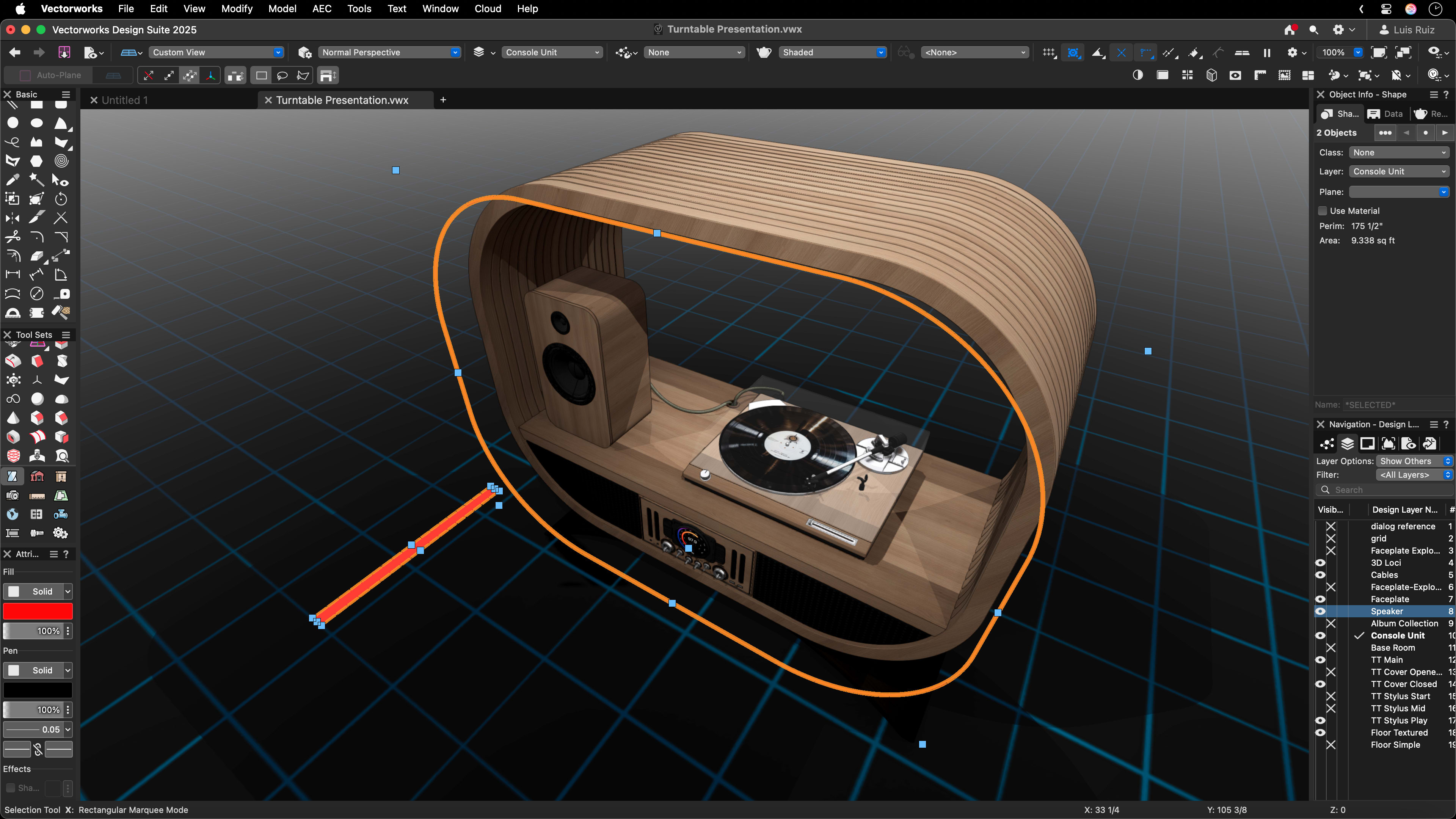
The Extrude Along Path command is a crucial one in your toolbelt that will extrude a profile object along a given path. You’ll need to draw two objects for this command — the first is your profile, which is a flat 2D representation of the shape you want the entire object to look like. The second is your path, which can be a simple line or NURBS curve.
This command was used to create the ribbed shell surrounding this turntable. In the image above, you can see a red rectangle that was used as the profile object. The orange ring was the path — after using the command, all that was left to do to form the shell’s shape was to copy and paste the extruded path until the desired result was achieved. Extrude Along Path was also used to create the cable connecting the speaker to the turntable.
History-Based Modeling
It’s not science fiction — you can go back in time in Vectorworks software.
This feature allows you to navigate back through modeling operations you took on an object. You’ll see a menu containing a selected object’s history in the Object Info Palette. Selecting an operation that you took from the list will highlight the area of the model affected by that operation.
One major advantage of History-Based Modeling is that you can copy and paste components from an object’s history to use in other parts of your model. If you want to reuse the same profile object on a new path for an Extrude Along Path command, for example, you can simply copy and paste the profile object from your original object’s history.

The modeling history of an object shown in a dropdown menu.
Texturing to add detail
Real-world objects often aren’t a singular, flat color. In this project, to achieve a more realistic texture on the record itself, our team found an image of a record online, then used the AI Visualiser to stylise that image. This stylised image was then saved as a texture to the Resource Manager, where you can easily apply it to the model.
The next step in your modeling journey
As you can see, all these modeling operations are incredibly simple to do, yet, when you add them all together, the result is much greater than the sum of parts. Whether you’re using On-Screen View Control for navigation or leveraging commands like Sweep and Extrude Along Path, these tools empower you to bring your creative visions to life.
3D modeling showcase
The post How to use key modeling commands in Vectorworks software appeared first on Planning, Building & Construction Today.